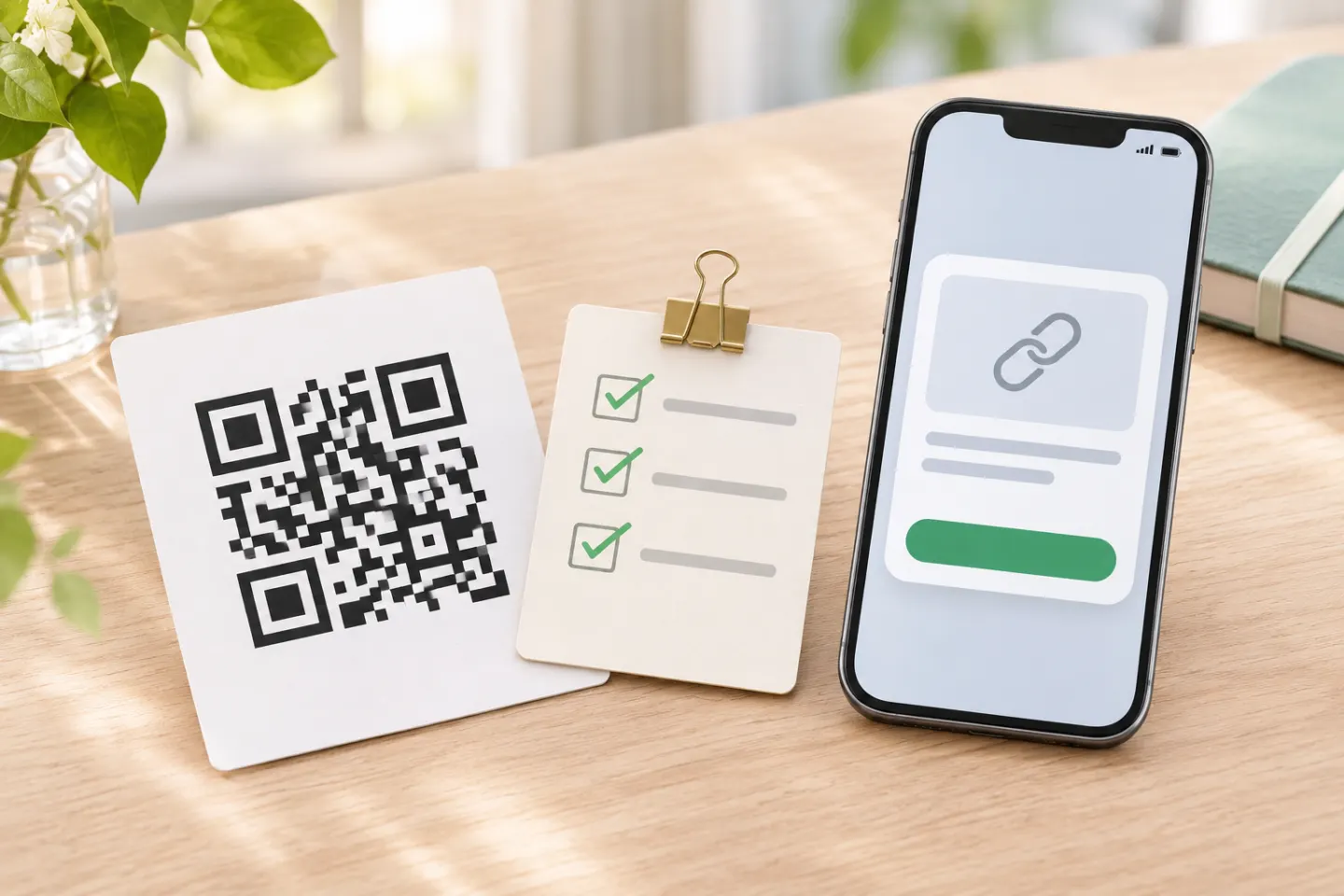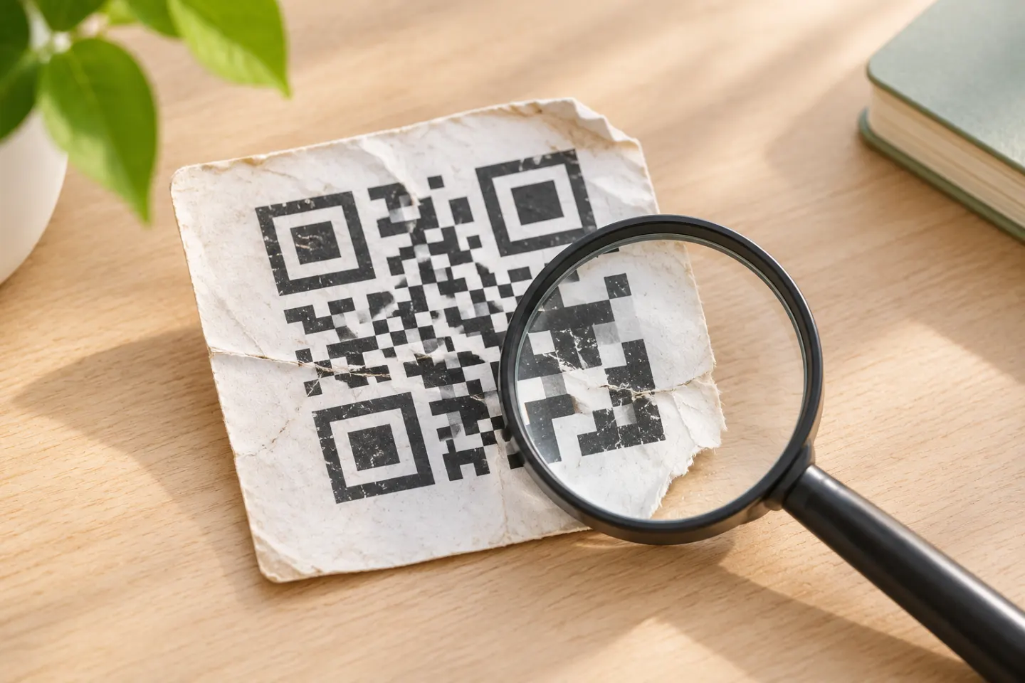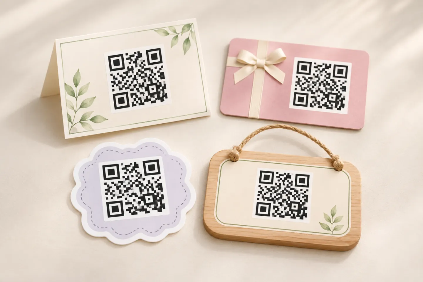


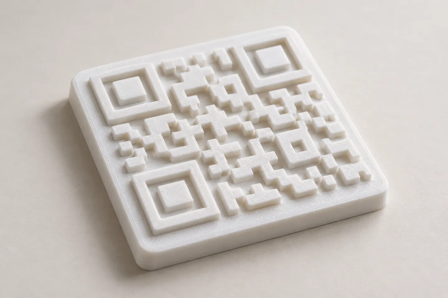
There is no universal relief height or minimum module size that guarantees every printer and phone will read a 3D printed code. The practical answer is to keep the geometry simple, check the sliced model, print a sample, and scan the physical part before making multiples.
What makes a 3D printed QR code different?
A regular QR image has light and dark modules on a flat surface. A 3D printed version encodes those modules in physical form: for example, light and dark filament regions, separate inlays, raised squares, or recessed squares. A flat, two-color face tends to make the light/dark pattern explicit. A single-material relief relies more on lighting and shadows, so its appearance can change with the viewing angle. Treat that as a design risk to test, not as a proven failure or success rule.
The QR symbol also needs its surrounding clear area. DENSO WAVE says a QR Code requires a margin four modules wide on every side, and explains that symbol version and module size determine the symbol’s dimensions.[1] In a 3D model, leave this border visually and physically clear: don’t let a frame, text, raised rim, or neighboring geometry intrude into it.
A practical design workflow
1. Start with a simple destination
Generate a QR code for the final URL or content, then scan that source image on a screen before modeling it. If you need to make a new static QR image, the QRHyper website lets you choose a content type, enter the fixed content, optionally customize the appearance, review the preview, and download a PNG. That PNG is only the source artwork: use a separate CAD or image-to-model workflow to prepare the geometry. QRHyper does not create an STL or manufacture the 3D printed part. Keep the encoded content as short as practical. A more complex code can contain more modules, which may make its individual features harder to represent at a given overall size. DENSO WAVE’s guidance shows how symbol version, module count, and module size relate to the overall code area.[1]
Do not add a logo or decorative pattern until the plain code works. If the destination changes after modeling, regenerate the code and repeat the whole design and print test; editing a few squares by eye can alter the pattern.
2. Choose a physical approach
For a first prototype, choose one of these approaches:
- Two-color face: Give the code modules and background visibly different materials or colors. A flat face keeps the encoded pattern easy to inspect.
- Raised or recessed modules: Use height or depth to create the pattern on a plain base. Keep the features broad and clean enough for the chosen printer and material, and avoid a finish that makes the modules merge visually.
- Separate insert or plate: Print the code face as a flat part and attach it to a larger object. This can make the code easier to position and replace if it does not scan.
These are design options, not a ranking of methods. A single-color raised pattern may look distinct from one angle and fade from another; a multicolor print may still fail if its edges blur or the code is too small. Test the actual combination of model, printer, filament, and surface finish.
3. Match detail to the printer and inspect the slice
Choose a code size that gives the printer enough room to reproduce each square and the border. Don’t set a universal number from another person’s setup: results depend on the printer, nozzle, material, orientation, and slicing settings. For FDM printing, Prusa’s nozzle guide explains that nozzle diameter affects detail mainly in the plane parallel to the print surface, while layer height affects detail on vertical and slanted surfaces; smaller nozzles can preserve finer text but take longer.[2] This is general printing guidance, not a QR-specific threshold.
Before printing, inspect the slicer preview closely. Check that every module remains separate, no narrow feature has disappeared, edges are not merged, the code has not been mirrored, and the quiet zone remains unobstructed. If the preview loses detail, enlarge the whole code or simplify its encoded content and generate a fresh symbol. Do not repair the modules manually unless you can validate the resulting code again.
4. Print and scan a prototype
Print one sample in the intended orientation, material, and finish. Scan the physical part rather than relying only on a screen preview or slicer image. Test the front under ordinary indoor light and at the distance and angle a user is likely to use. If the part will be mounted, curved, handled, or used outdoors, include those conditions in the test.
Try more than one phone if possible. Apple’s instructions describe using the Camera app or Code Scanner, holding the device so the code appears, and tapping the link.[3] Google’s Pixel guidance recommends keeping the whole code in view; its troubleshooting advice includes holding steady, using good light, avoiding glare and shadows, and moving closer while keeping the full square visible.[4] Record whether the code opens the correct destination on each device, not just whether a scan animation appears.
| Prototype check | What to confirm |
|---|---|
| Pattern | All light/dark modules are visually distinct; no features merged or vanished in the sliced and printed model. |
| Clear border | The four-module margin is preserved on every side and is not crossed by a frame or text.[1] |
| Contrast and angle | The pattern stays distinguishable in the light and from the viewing angle expected in use. |
| Scan distance | A user can scan from the intended position without needing to guess or repeatedly re-aim. |
| Destination | The printed part opens the correct page on the available phone types. |
| Durability, if relevant | A handled or exposed sample is checked again after representative wear or cleaning. |
If the code fails, troubleshoot one factor at a time: enlarge the code, simplify the encoded destination, increase the visual separation between foreground and background, flatten or reposition the code face, or adjust the print orientation. Then inspect the slice and print another sample. Do not assume that adding more height alone will solve a contrast or geometry problem.
Common reasons a 3D printed QR code fails
- The code looks right in CAD but not in the slicer: Fine modules may be dropped or joined at the selected printer settings. Check the sliced preview and increase the overall size if necessary.[2]
- The pattern changes with the light: A single-material relief may rely on shadows. Retest with a flatter or higher-contrast design and representative lighting.
- A border or frame touches the code: Restore the four-module clear margin around the symbol.[1]
- The phone sees only part of the code: Adjust the scanning distance so the whole square fits in the camera view.[4]
- A successful scan opens the wrong page: Verify the final destination and regenerate/retest the code after any link change.
Final decision
A 3D printed QR code is feasible as a design project, but scan reliability must be demonstrated on the printed part. Start with a simple code and clear geometry, preserve the required quiet zone, inspect the sliced file, then test the sample on real phones in realistic lighting and at the intended distance. If the physical prototype does not scan consistently, revise it before making the final object.
References
[1] DENSO WAVE. “Point for determining the code area.” https://www.qrcode.com/en/howto/code.html
[2] Original Prusa 3D Printers. “Everything about nozzles with a different diameter.” https://blog.prusa3d.com/everything-about-nozzles-with-a-different-diameter_8344/
[3] Apple Support. “Scan a QR code with your iPhone or iPad.” https://support.apple.com/en-us/102680
[4] Google Pixel Phone Help. “Scan QR codes with your Pixel phone.” https://support.google.com/pixelphone/answer/16561572?hl=en