

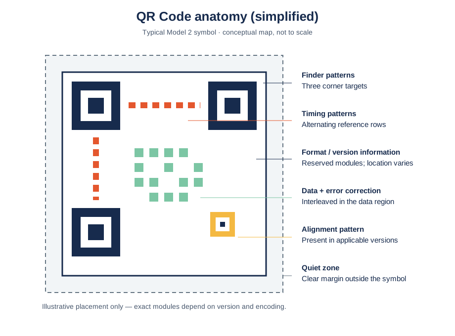
It is a simplified map of a typical QR Code Model 2 symbol, not a bit-accurate rendering or a scale drawing. Exact placement varies by version; some features only appear in higher versions. [1]
The main parts at a glance
| Part | Where to look | What it helps the reader do |
|---|---|---|
| Finder patterns | Three large squares at the top-left, top-right, and bottom-left | Locate the symbol and estimate its orientation |
| Timing patterns | Alternating modules between the finder patterns | Determine the module spacing and grid |
| Alignment patterns | Smaller target-like patterns in larger symbols | Help correct for distortion or perspective |
| Format information | Small reserved strips near the finder patterns | Recover error-correction level and mask pattern |
| Version information | Reserved areas in versions 7 and above | Identify the symbol version |
| Data and error-correction codewords | The remaining encoded region | Recover the payload and help reconstruct damaged data |
| Quiet zone | Clear margin outside the symbol | Separate the symbol from surrounding marks |
This map describes the common Model 2 QR Code. Other related formats, such as Micro QR, have different layouts. Do not use this diagram as a production template. [1][2]
Finder patterns: the three corner targets
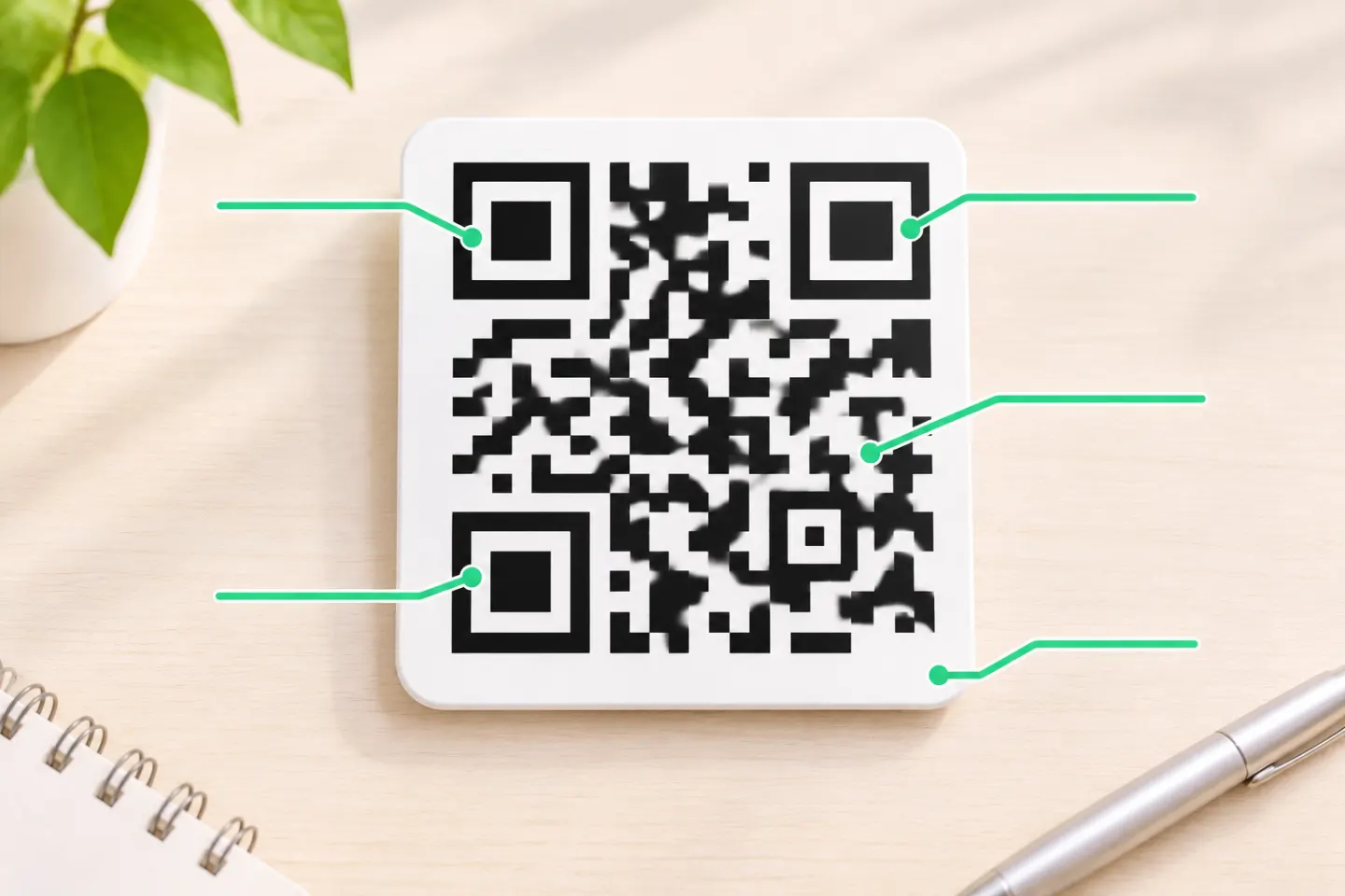
The three large square patterns appear at the upper-left, upper-right, and lower-left corners of a standard Model 2 symbol. Their distinctive nested-square design helps a reader identify the symbol, estimate its orientation, and locate the grid even when the code is rotated. They are not decorative logos and do not contain the website address. [1]
A practical consequence: if a printed mark, crop, or logo obscures one of these corners, a reader may have trouble locating the symbol even when much of the data area remains visible. Error correction is not a substitute for preserving essential positioning features.
Timing and alignment patterns: mapping the grid
The timing pattern is a sequence of alternating dark and light modules that runs horizontally and vertically between finder patterns. It gives the decoder a reference for module spacing and helps it map the cells between corners. [1]
Alignment patterns are smaller target-like features used to compensate for image distortion. A symbol may contain one or more of them depending on its version; a Version 1 symbol does not have one. They are not interchangeable with finder patterns: the three corner patterns establish the broad position and orientation, while alignment features help refine geometry in larger symbols. [1]
Format and version information
The symbol reserves particular modules for format information. This encodes the error-correction level and the mask pattern used to make the data pattern easier to read. The mask is a standard pattern applied during encoding; the reader uses the recorded format information to reverse that step while decoding. [1]
Version information appears only in versions 7 through 40. It identifies the symbol version, which corresponds to the grid’s dimensions. DENSO WAVE describes Model 2 versions from 1 (21 × 21 modules) to 40 (177 × 177 modules), adding four modules per side at each version increase. [2]
Data modules and error correction
The dark and light modules in the data region represent encoded data and error-correction codewords. It is misleading to picture error correction as one separate visible patch: the codewords are encoded into the data region along with the payload. A QR decoder reads the pattern and uses redundant codewords to recover data when some modules are unreadable. [1][3]
DENSO WAVE documents four error-correction levels: L, M, Q, and H. Higher correction adds redundancy and generally leaves less capacity for the original payload at a given symbol size. Its approximate recovery figures are proportions of total codewords under the specification’s model, not percentages of the image that can always be covered or scratched away. [3]
Quiet zone: blank margin outside the code
The quiet zone is the unprinted, clear area around a symbol. It is outside the encoded grid; it is not an extra row of data modules. This margin helps scanning software distinguish the symbol from nearby text, borders, images, or other marks. Keep the area clear when placing a code in a layout. The required width is defined relative to the symbol’s module size, not a fixed number of pixels. Use the applicable QR Code specification and the requirements of the intended reader when preparing production artwork. [1]
A white border drawn as part of a graphic does not automatically guarantee a quiet zone if nearby content intrudes into that space. Measure the margin relative to the module size, not in a fixed number of pixels.
Why version changes the pattern
As more information is encoded, the symbol may need more modules. QR Code Model 2 uses versions 1–40, with different grid dimensions; alignment features and version information therefore depend on the version. This is why one generic diagram cannot show every QR Code’s precise module placement. [2]
The same principle explains why a long URL or large payload often creates a denser symbol: the code must represent more data, and error correction adds its own codewords. The anatomy stays recognizable while the detailed placement changes.
Common misreadings
- “The three big squares store the link.” They are finder patterns that help locate and orient the symbol. The payload is represented in the data region. [1]
- “The blank edge is part of the QR grid.” The quiet zone surrounds the symbol; it is not encoded data. [1]
- “Thirty percent of the picture can always be covered.” Recovery levels describe codeword recovery, not a guarantee about arbitrary image area or damage location. [3]
- “Every QR code has all the same features.” Version-dependent areas differ; for example, version information is used only from version 7 onward. [1][2]
- “A diagram tells me where to put a logo.” This schematic explains function, not safe design placement. A design can interfere with scanning even if the diagram appears to leave open space.
Frequently asked questions
What are the three big squares in a QR code?
They are finder patterns. They help a scanner detect the symbol and estimate its position and orientation. [1]
What is the difference between a finder pattern and an alignment pattern?
Finder patterns are the three large corner targets used to locate and orient the symbol. Smaller alignment patterns help correct geometric distortion in applicable versions. [1]
Where is the error-correction area?
There is no single isolated visible block labeled “error correction.” Error-correction codewords are encoded in the data region along with payload data. [1][3]
How wide should the quiet zone be?
The required width is defined relative to the symbol’s module size, not a fixed number of pixels. Use the applicable QR Code specification and the requirements of the intended reader when preparing production artwork. [1]
References
[1] Scandit. “QR Codes: Complete Technical Guide.” https://www.scandit.com/products/barcode-scanning/symbologies/qr-code/
[2] DENSO WAVE. “Information Capacity and Versions of QR Code.” https://www.qrcode.com/en/about/version.html
[3] DENSO WAVE. “Error Correction Feature.” https://www.qrcode.com/en/about/error_correction.html